CyberBrick: Bambu Lab’s Answer to Printed Robotics
CyberBrick is designed as an ecosystem for building and sharing printable robots. This article examines how it works, the build experience, and the risks of a closed platform.


From a practical point of view, 3D printing has largely been about producing objects, enclosures, brackets, and models that serve a fixed purpose once printed. Robotics follows a different path, where physical parts are only one piece of a larger system that also includes electronics, firmware, and control. Bringing those two worlds together has traditionally required significant integration work.
CyberBrick is Bambu Lab’s attempt to bridge that gap. It combines printable designs with a predefined set of electronic modules, allowing functional robots to be assembled from a shared hardware foundation. Builders can focus on creating designs with embedded robotics without needing deep expertise in electronics or managing how those components are sourced.

This article examines CyberBrick from three perspectives: how the system is structured, what it is like to build with, and how viable the hardware remains if the ecosystem is no longer supported.
What is Cyberbrick?
CyberBrick is Bambu Lab’s attempt to bring modularity to 3D printed robotics. The system is built around a set of standardized electronic modules, controllers, motors, servos, and connectors, that printed models can be designed to accommodate. Instead of building custom electronics for each project, designers shape their models around these predefined components, allowing the same hardware to be reused across very different builds. It's a construction system for robots, where different designs share a common foundation. In practice, building a CyberBrick project means printing the 3D shell and integrating the electronics during assembly.

Once assembled, the system still needs to be configured before anything moves. Both the controller and the vehicle require updated firmware to be installed, along with project-specific code to enable communication and control. Bluetooth is used for setup tasks such as flashing firmware and transferring code, while a separate 2.4 GHz link handles real-time communication between devices once paired. At this stage, the project shifts from assembly to configuration, with a focus towards software and connectivity.

The assembly guides read less like instructions for a kit and more like documentation for a small mechanical system. They walk through gear assemblies, wiring layouts, and component placement with the expectation that the builder has some familiarity with electronics. This is a clear distinction from most robotics kits explored on Technodabbler, such as the CrunchLabs Hack Pack, where the focus is on guided learning and understanding how each component works. Those kits are structured to teach concepts step by step. CyberBrick takes a different approach, assuming the system works as a whole and focusing instead on assembling a complete, functional design.
Cyber Bricks
CyberBrick is built around a small set of reusable modules that define how each project behaves. Rather than introducing new electronics for every model, the same components are reused across the controller, truck, and forklift, with the printed parts adapting around them. This consistency is what allows different builds to share the same underlying system.

At the center of that system are the controller and remote shields, which define how inputs and outputs are connected. The controller shield is designed for user input, exposing six analog ports and four digital ports to support joysticks, switches, and buttons. The remote shield, on the other hand, is focused on actuation, with dedicated ports for two motors, two LED outputs, and four servo connections. Both shields interface with the same underlying compute unit, built around an ESP32-C3, which handles communication, control logic, and firmware execution. The controller and remote communicate over a 2.4 GHz link during operation. In practice, the ESP32-C3 provides a fixed number of GPIO pins, and the different shield designs map those pins to specific functions, allowing the same compute unit to support different roles depending on the location in the build.

Input is handled through a mix of analog and digital components connected to the controller shield. Analog inputs measure a range of values rather than a simple on or off state, which allows joysticks to report position continuously across an axis: small movements translate into gradual changes in speed or direction. In contrast, the rocker switch and momentary button use digital inputs, which only register discrete states such as pressed or released. In practice, analog inputs are well suited for controlling motors and servos with smooth, progressive movement, while digital inputs are better used for state changes such as toggling lights or triggering specific actions.

On the output side, motion is handled through motors and servos connected to the remote shield. DC motors provide continuous rotation and are used for driving wheels or tracks, where speed and direction are controlled directly. Servos, by contrast, are controlled through position-based signals. A 180-degree servo moves to a specific angle, making it suitable for mechanisms such as lifting or steering. A 360-degree servo removes positional control and instead rotates continuously, with direction and speed determined relative to a neutral signal. This allows it to function as a controlled rotational actuator, sitting somewhere between a positional servo and a traditional motor.

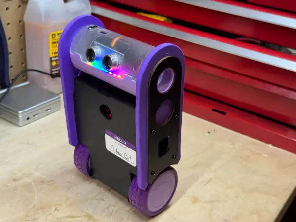
Lighting is handled through an LED hub that groups multiple outputs into a single module. Unlike many robotics kits that use single-color LEDs, these are RGB, which allows for more flexible feedback. They are also surprisingly bright, and should be used with some for, of diffusion.. Without any diffusion, the light is intense enough that they require diffusion.

Taken together, these modules form a consistent hardware layer that power every CyberBrick project.
Building with CyberBrick
Before looking at the system in the abstract, it helps to understand what it actually takes to build with CyberBrick. The process is not a simple assembly of parts, but a combination of printing, mechanical fitting, firmware setup, and system configuration. The following sections walk through that experience, from initial setup to completed models, and highlight where the system works well and where it introduces friction.
Start with the Electronics
One of the most important lessons from this build came before any mechanical assembly. Rather than starting with printed parts, it is far more effective to begin by connecting all the electronic components, flashing the firmware, loading the project code, and verifying that everything works as expected. This step is not emphasized in the official process, but it significantly reduces the complexity of debugging later on.

Establishing a stable setup was not straightforward. Bluetooth connectivity proved inconsistent across both iOS and PC, particularly when attempting to pair devices or transfer code. At one point, a firmware update failed mid-process, leaving one of the control units unresponsive. Recovering from this required stepping outside the standard workflow and using the dedicated flashing tool, which provided better visibility into the device state and allowed recovery over USB-C.

That tool ultimately became essential. Beyond recovering a failed unit, it also made it possible to flash firmware directly over USB-C, which was both faster and more reliable than Bluetooth. It also exposed options to reset connection settings, which helped resolve pairing issues between the controller and the vehicle. Once both units were properly configured and tested, the rest of the setup became far more predictable.

Taking the time to validate the electronics upfront changes the entire experience. Without that step, it becomes difficult to determine whether a problem comes from the build, the firmware, or the communication layer. With it, the system can be treated as known-good before being enclosed in a complex mechanical assembly.
The Controller
The controller serves as the first full assembly of the system, and sets the baseline for what to expect from a CyberBrick build. After validating the electronics, the focus shifts to fitting the printed parts around the components and bringing everything together into a usable device. On paper, this is a straightforward enclosure build. In practice, it requires more adjustment than expected.

The main challenge comes from tolerances. Several pieces of the casing did not fit cleanly and required manual trimming to come together properly. This was not limited to a single component. Parts from both controller prints had to be mixed to achieve a workable fit, including elements of the outer shell and joystick assembly. The complexity of the geometry, combined with heavy use of supports that are difficult to remove cleanly, leads to parts that are close, but not always precise enough for a smooth assembly. Because of the tight tolerances, even small imperfections from support removal can prevent pieces from fitting correctly.

Even small details reinforced this pattern. The top flap did not close properly despite the presence of a magnet, and that same magnet required additional force, and even drilling, to fit into place. These are not major structural issues, but they accumulate and slow down the build process, turning what should be a simple enclosure into a series of small adjustments.

The electronic side of the controller is, by comparison, straightforward. Components connect cleanly, and once assembled, there is little ambiguity in how they fit together. However, at this stage, there is no easy way to validate the final build. Without a paired vehicle or loaded project, the controller cannot be meaningfully tested, which makes it difficult to confirm whether the assembly is fully correct until later in the process.
The Truck
Unlike the controller, which is focused on input, the truck is a fully mechanical build. It introduces a drivetrain, steering system, and multiple moving parts that all need to work together. That shift makes the build far more sensitive to fit, alignment, and overall precision.

The first issue appeared early in the assembly when two parts of the front axle broke during installation. These components had to be reprinted, this time using a denser PETG configuration to improve strength. Even after that, assembly remained difficult. Many parts did not fit cleanly and required force to come together, with some pieces needing light hammering to seat properly. Tight tolerances, combined with small inconsistencies from printing and support removal, made the process feel more like adjustment than assembly.

Part of that friction came from the order of operations. Starting the assembly before validating the electronics made troubleshooting far more difficult. The instructions suggest actions such as resetting the servo during assembly, but without firmware loaded, the system does not respond. The controller and compute units ship as a blank slate, which is not clearly explained in the documentation. As a result, several steps appeared to fail, when in reality the system was simply not initialized yet. This is where the earlier lesson became clear: test and configure everything before assembling.

Once the build was complete and the firmware loaded, the system still did not behave correctly. Steering and rear drive were both off, which required partial disassembly to test components individually. After reassembling, everything worked as expected, suggesting that alignment or fit was the issue. Even then, some details never came together cleanly. The doors, for example, never quite close properly, which becomes hard to ignore once the rest of the system is working.

The end result is functional, but getting there takes time and patience. Between assembling the controller, building the truck, and setting up the software, the process took around four hours, not including print time.
The Forklift
After the truck, the forklift is a very different experience. It uses the same components and follows a similar process, but the fit and tolerances are noticeably better. Parts come together cleanly, with almost no need for trimming or force. That alone changes the pace of the build.

The difference is not just in fit, but in how the model is designed. The forklift feels more thought through. Covers are held in place with properly sized magnets, the battery is easy to access and replace, and the electronics are easier to reach during assembly. Even small details, such as how components are layered and secured, make maintenance feel more manageable. Functionally, it also goes further than the truck. In addition to driving, the forklift introduces a lifting mechanism, adding another level of interaction to the build.

This time, all electronics were connected, flashed, and tested before assembly began. That made it possible to validate components as the build progressed, instead of discovering problems at the end. It is a simple change, but it removes much of the uncertainty that slowed down the truck build.

The contrast between the two models is hard to ignore. The quality of the design has a direct impact on the build experience, even when using the same hardware and following the same general process. The truck feels demanding and inconsistent, while the forklift comes together cleanly and works as expected. These are both official models, not community builds, which makes that difference even more noticeable.
Long-Term Viability of the Platform
After working through the build, a clearer picture of the system begins to emerge. Beyond the individual models, CyberBrick reveals itself as a platform with specific design choices and constraints. Understanding how those choices compare to more open approaches, and what they imply for long-term use, is key to evaluating where the system fits.
A Closed System by Design
CyberBrick is built as a tightly integrated system, where the hardware, firmware, and tooling are designed to work together within a controlled environment. While the individual components are modular, they do not operate independently. The controller and remote units rely on Bambu’s firmware, configuration tools, and communication stack to function as intended.

This becomes most apparent during setup and recovery. Firmware must be loaded using Bambu’s tools, and in cases where an update fails, recovery depends on access to their dedicated flashing utility. In practice, this means that even though the hardware is based on standard components such as the ESP32-C3, interacting with it outside of the intended workflow is not straightforward. The system assumes that configuration, pairing, and updates will all be handled through the provided ecosystem.

The same applies to communication. Bluetooth is used for setup and code transfer, while a 2.4 GHz link handles operation between devices. Both layers are abstracted behind Bambu’s tooling, which simplifies the process when everything works, but limits visibility and control when it does not. Troubleshooting becomes dependent on the tools and documentation provided, rather than on direct access to the underlying system.

This level of control is not accidental. For designers creating printable robots, the challenge is not just building a working prototype, but ensuring that others can reproduce it reliably. A tightly integrated system removes much of that uncertainty by standardizing the electronics, communication, and setup process. In that context, CyberBrick is less about flexibility and more about consistency. It provides a foundation where designs can be shared and assembled with predictable results, as long as everything stays within the system.
3.2 Compared to Open Platforms
To understand CyberBrick’s design choices, it helps to compare it to more open platforms such as Arduino or ESP32-based projects. These platforms expose the hardware directly through their GPIO pins, which can be used to read digital signals, measure analog values, or control external components. In practice, this makes them extremely flexible. A single controller can interface with a wide range of sensors, actuators, and communication modules, depending on how it is wired and programmed.

Crunchlab's Hackpack is an alternative ecosystem targeted at young adolescent wanted to learn robotics.
That flexibility comes with added complexity. Each component typically requires its own code, libraries, and configuration. Driving a simple sensor is straightforward, but controlling motors often requires additional hardware such as motor drivers, each with their own interfaces and software requirements. Unless the hardware is already familiar or well supported, getting a system working can quickly become a process of trial, error, and integration.

Micro:bit, combined with the proper hardware, can be a very accessible robotic experience.
The same applies to communication. Many of these platforms support Wi-Fi, Bluetooth, or even cellular connectivity, but debugging issues often requires working at a low level, inspecting signals, logs, and code directly. There is no single, unified workflow, and the responsibility for making everything work falls entirely on the builder.

At the other end of the complexity spectrum, you can grab an Arduino board and different electronics.
This is where the value of a closed system like CyberBrick becomes more apparent. By defining how components connect, how they are controlled, and how they communicate, it removes much of that uncertainty. The trade-off is clear: flexibility is reduced, but the path to a working system is more predictable.
What Happens If Bambu Walks Away
The reliance on Bambu’s tooling raises a practical question: what happens if support for CyberBrick is reduced or discontinued. The system depends on their firmware, flashing tools, and communication stack to function as intended. That integration simplifies the experience, but it also means the platform is not fully self-contained. The build process already assumes access to these tools, whether for initial setup, firmware updates, or recovering from failures.

At a hardware level, CyberBrick would not become unusable overnight. The core of the system is based on an ESP32-C3, and the surrounding components, motors, servos, buttons, and LEDs, are standard enough that they could be driven by alternative firmware. The shields expose structured connections, but they ultimately map back to GPIO pins. With enough effort, the hardware could be repurposed as a more traditional ESP32-based robotics platform, even if it no longer follows the original CyberBrick workflow.
The challenge is in everything that sits on top of that hardware. The current system relies heavily on Bambu’s tools for firmware flashing, recovery, and configuration. In practice, these tools are not optional. A failed firmware update requires access to the official flashing utility, and even normal setup depends on their software for loading code and managing connections. Without these tools, users would need to replace not just the firmware, but also the process used to deploy and maintain it.
import machine
import neopixel
import time

pin = machine.Pin(8, machine.Pin.OUT)
np = neopixel.NeoPixel(pin, 1)

np[0] = (255, 0, 0)  #(R, G, B)
np.write()
You can use MicroPython to control peripherals such as GPIO, I2C, and PWM. For example, to light up the onboard RGB, initialize the neo library on the correct pin and send a signal.
The software layer adds another constraint. While parts of the CyberBrick codebase are available, they depend on underlying modules that are not fully exposed. These modules handle key functions such as communication and device control, and their absence means the full behavior of the system cannot be recreated directly from published sources. Rebuilding that functionality would require reimplementing those interfaces or designing alternatives, which turns the effort into a more involved engineering task rather than a simple adaptation.
There is also a legal dimension to consider. The available source code is not fully open, and its license restricts usage to Bambu’s ecosystem, including MakerWorld services and products. Even if the technical challenges could be addressed, extending or redistributing the existing software outside of that context would likely require a clean reimplementation rather than a direct reuse of what has been published.
CyberBrick Codebase License:

Copyright (C) 2025 MakerWorld

Permission is hereby granted, free of charge, to any person obtaining a copy of this software and associated documentation files (the "Software"), to use, copy, modify, reproduce and distribute (the "Use") the Software, subject to the following conditions:

1. Only Use in MakerWorld
The Software may only be used through services, programs, or products provided by MakerWorld, or those expressly authorized by a written license from MakerWorld. When using the Software, strict compliance with MakerWorld's Terms of Use and Community Guidelines is mandatory.

2. Derivative Works
You may reproduce and distribute copies of your derivative works based on the Software (the "Derivative Works") under the license of Article 1.
You may add Your own copyright statement to Your modifications and may provide additional or different license terms and conditions of Your modifications, or for any such Derivative Works as a whole.
3. License Notice
This License including but not limited to the copyright of MakerWorld shall be included in all copies or substantial portions of the Software.

THE SOFTWARE IS PROVIDED "AS IS", WITHOUT WARRANTY OF ANY KIND, EXPRESS OR IMPLIED, INCLUDING BUT NOT LIMITED TO THE WARRANTIES OF MERCHANTABILITY, FITNESS FOR A PARTICULAR PURPOSE AND NONINFRINGEMENT. IN NO EVENT SHALL THE AUTHORS OR COPYRIGHT HOLDERS BE LIABLE FOR ANY CLAIM, DAMAGES OR OTHER LIABILITY, WHETHER IN AN ACTION OF CONTRACT, TORT OR OTHERWISE, ARISING FROM, OUT OF OR IN CONNECTION WITH THE SOFTWARE OR THE USE OR OTHER DEALINGS IN THE SOFTWARE.
The CyberBrick license is very explicit that the Core code is provide solely to be used in the MakerWorld ecosystem.
In practical terms, the effort falls into three categories. At the lowest level, the hardware could be kept useful without too much difficulty. The ESP32-C3 platform and standard components make it possible to write new firmware and reuse the motors, servos, and inputs in a more traditional setup. At the next level, recreating most of what CyberBrick provides today becomes significantly more involved. This includes rebuilding the MicroPython application layer, replacing the native modules it depends on, and reimplementing the communication stack used for setup and control. At the highest level, preserving the full CyberBrick experience, including its tooling, pairing process, and integrated workflow, would require substantial engineering effort, effectively rebuilding the platform.
Who Is CyberBrick For?
Working through the full build raises a simple question: who is this system actually for. It does not clearly align with the typical audiences of robotics kits, and the experience sits somewhere between a guided product and a development platform.

For beginners, the barrier to entry is high. The build process requires managing 3D printing constraints, dealing with tight tolerances, assembling mechanical systems, and handling firmware and connectivity issues. The documentation assumes a level of familiarity with both electronics and mechanical assembly, and there is little in the way of guided learning. When something does not work, the system does not provide much help in understanding why.
At the other end of the spectrum, experienced builders may find the system restrictive. Platforms such as Arduino or ESP32 offer direct control over hardware, flexible integration with a wide range of components, and well-understood development workflows. CyberBrick, by comparison, defines how components are connected and used, and limits how far the system can be extended beyond its intended design. For someone comfortable building custom solutions, that level of constraint may feel unnecessary.

The more convincing answer is that CyberBrick is designed for a different role. It targets makers who are comfortable with 3D design and want to create functional robotic models without building the underlying electronics from scratch. By standardizing the hardware, Bambu provides a known foundation that designers can build around, allowing their models to be reproduced by others using the same components.
This is where the system connects directly to MakerWorld. A designer can create a printable robot, knowing that the required electronics are available as a kit and behave in a predictable way. Users can then print, assemble, and run that design without sourcing parts or adapting code. The value of CyberBrick is not in teaching robotics or enabling full customization, but in making robotic designs easier to distribute and reproduce.

In that sense, CyberBrick is less a robotics kit and more a platform for packaged designs. It shifts the focus away from building electronics and toward creating systems that others can assemble and use. And although CyberBrick has some rought edges, it ultimately succeeds at creating a rich robotic ecosystem for the maker space.
Have you tried building a functional robot from a 3D printed design, or worked within a system like CyberBrick? Share your experience in the comments, especially if you approached it from the design side rather than electronics. If you want to explore a more open approach to building robotics, take a look at our article on creating a 3D printed robot using the micro:bit platform, where the hardware and software stack are fully under your control.